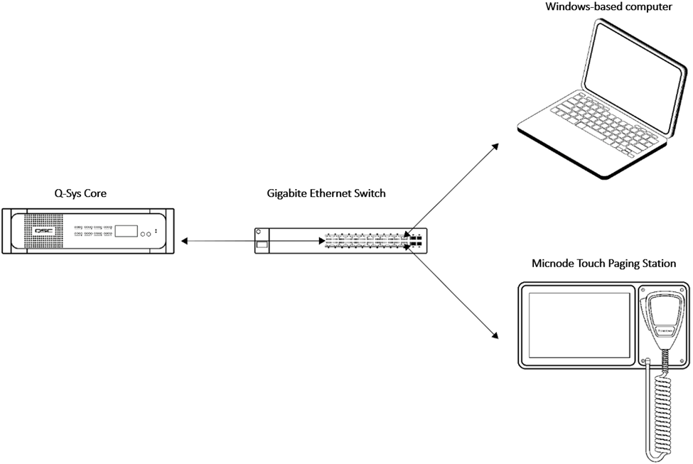
The Micnode Touch Paging station is connected to the network via a standard ethernet cable. This network consists of:
Q-Sys Core
Windows-based computer for Q-Sys designer network setup, not required for runtime operation,
Gigabit Ethernet Switch with PoE ports.
Note: In factory settings Micnode is configured to obtain IP addresses automatically from a DHCP server.
Network overview:
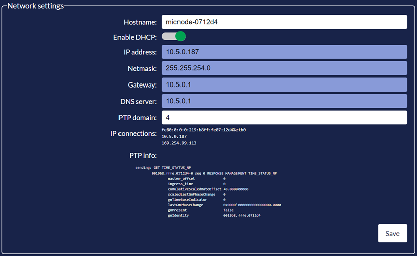
A) Network settings in Micnode
Once the network is connected, network settings are defined in the paging station’s network settings section. First you will need to login and then select the Network settings:
The Hostname is the assigned device label,
Below that is the On/Off switch for enabling DHCP. Data is pushed automatically but can be changed when switched off. The following four fields are editable – IP address, Netmask, Gateway, and DNS server,
PTP (Precision Time Protocol) domain has a counter when scrolling over it. The values need to be aligned with the Q-Sys designer properties.
Important: Save your settings to be applied.
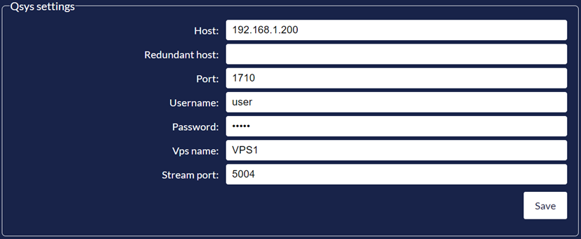
B) Qsys settings
The Micnode Touch Paging Station settings configure the Q-Sys relevant information as:
Host,
Redundant host,
Port,
User authentication to Q-Sys Designer,
Vps name,
Stream port.
C)Configuration in Q-Sys Designer
The Micnode Touch Paging Station needs to be configured in Q-Sys Designer and connected to a PA router and, therefore, the following configuration is required to be set up in Q-Sys Designer:
Go to File > New Design, or open an existing one with setup PA router.
Add a new Virtual Paging Station (VPS) and configure it:
Rename the Virtual Paging Station – for example VPS1,
Set priority,
Change Mode to ‘Live’,
Enable Robot Controls,
Define Zone Group Count – number of zones for the Micnode Touch Paging station,
Script - needs to be enabled,
Pick zones or tags, if not available click F6 – File > Emulate.
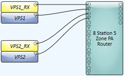
Add a new inventory item – Streaming I/O – AES67 Receiver.
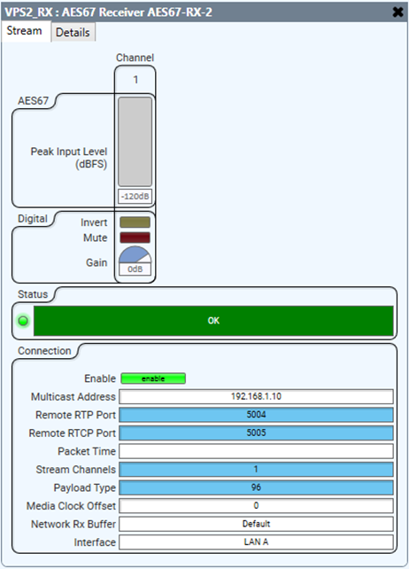
D)Q-Sys - Configure the receiver:
Rename the receiver – name it the same as the Virtual Paging station with suffix _RX – for example VPS1_RX,
Set the Connection mode to ‘Manual’,
Set the Channel count to one,
Connect the receiver with the PA router.
Connect the Virtual Paging Station with the PA router.
Important: As the naming convention connects the elements, the receiver and VPS need to have the same name, and the receiver must have a suffix.
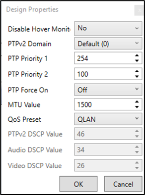
E) Q-Sys Design properties PTPv2 Domain needs to be set to the same values as the Micnode Touch Paging Station; Settings > Qsys Settings > PTP domain.
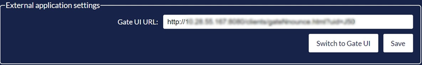
F)External application settings Insert the URL to the app that is to be displayed on the paging station screen as UI. Confirm the URL by tapping the ‘Save’ button.
To configure GateUI on your Micnode Touch Paging station see the next chapter: Configure GateUI