Features
- 26 Jan 2026
- 1 Minute to read
- Print
- Download PDF
Features
- Updated on 26 Jan 2026
- 1 Minute to read
- Print
- Download PDF
Article summary
Did you find this summary helpful?
Thank you for your feedback!
Description
Front and rear panel of the micnode2 microphone station.
A. Front panel
| 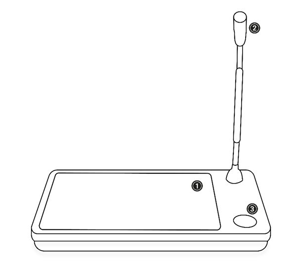 |
Touch screen The 8-inch touch display shows the user interface operating the microphone station. For more information, see the chapter on User interfaces setup. Use your fingers to touch the screen. CAUTION: Don’t use any sharp objects on the screen. Clean the screen with static-free cleaning cloths only. Microphone The gooseneck microphone is bendable and can be adjusted to the speaker’s needs. This microphone is attached to the microphone station and can be replaced if needed. The Talk/Start button is on the microphone station below the microphone. | |
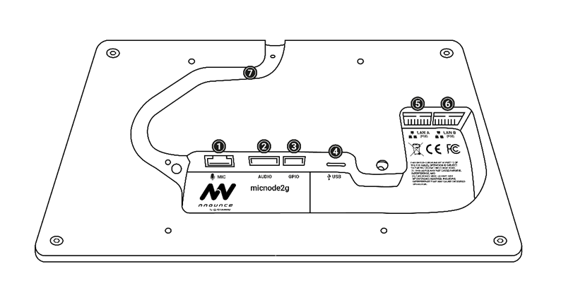
B. Rear panel
IMPORTANT: USB port serves only for recovery purposes. |
|
| Power The LAN cables connect the paging station to the network. This enables audio and data exchange as well as receiving power from the LAN network via IEEE 802.3af compliant power sourcing equipment (PSE), also known as Power-over-Ethernet (PoE). Inputs and outputs On the rear panel of the micnode2 microphone station, it is possible to connect a variety of auxiliary audio I/O and GPIO (General Purpose Input Output). Different devices or accessories can be connected e.g. a secondary microphone or an MP3 audio source can be added. LAN A & B The two LAN switches allow simultaneous connection to the audio and control networks, or the second LAN can be used for a redundant network. | |
Was this article helpful?