Description
Front and rear panel descprition of control leds, ports and connectors.
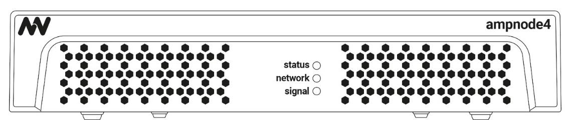
A. Front panel The front panel has 3 control LEDs: - status
- network
- signal
|  |
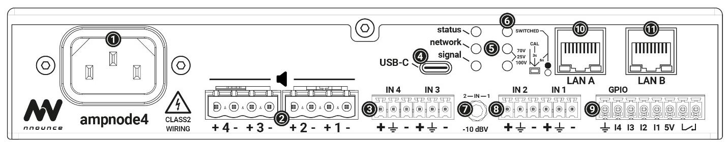
B. Rear panel Description from left to right.- Power connector IEC C14 100-240 VAC @ 50-60 Hz
- Speaker terminals (70/100V Hi-Z, Low-Z)
- Balanced audio IN4 and IN3
- USB-C
- Control LEDs
- Limiter Switch
- Jack input
- Balanced audio IN2 and IN1
- GPIO - Control inputs/output
- LAN A with PoE
- LAN B with PoE
Note: The two LAN switches allow simultaneous connection to the audio and control networks, or the second LAN can be used for a redundant network.
| Control LEDs on the left-side from the LAN: - status
- network
- signal
- 70V / 100V
- switched
|
Product sticker on device bottom contains MAC address required for device pairing.
Control LEDs
Front panel and rear panel LEDs are aligned, the description below is valid for both.
Status | Device status: - Red LED light indicates booting of the device.
- Yellow LED light indicates that the operating system successfully booted and services are starting.
- Green LED light indicates all services are up and running.
|
Network | Network connection availability check: - LED light is off, no network connection.
- Blue LED light when auto mode active and no IP obtained from DHCP. Device available only through IPv6 link local.
- Green LED light when at least one active interface is available with correct IP address.
NOTE: The indicator is not available until all services are in operation. |
Signal | Green LED lights up if DSP and the design are running. NOTE: The indicator is not available until all services are in operation or the DSP design is empty or missing. |
70V /100V | Green LED lights up according to limiter setting match: - Limiter setting is 70V, LED for 70V lights up,
- Limiter setting is 100V, LED for 100V lights up,
- Limiter setting is 25V then both LEDs light up 70V and 100V.
NOTE: The indicator is not available until all services are in operation. |
Switched | Reserved for future use. |